B C
-
Posts
9373 -
Joined
-
Last visited
-
Days Won
668
7 Followers


About B C

- Birthday 05/12/1989
Recent Profile Visitors
5693 profile views


B C's Achievements
")


-
 Jdesign reacted to an answer to a question:
Suspension/part coating Suggestion
Jdesign reacted to an answer to a question:
Suspension/part coating Suggestion
-
Jdesign reacted to a post in a topic:
chit chat thread
-
Boris3 reacted to a post in a topic:
chit chat thread
-
 B C reacted to a post in a topic:
chit chat thread
B C reacted to a post in a topic:
chit chat thread
-
 KaiserRolls reacted to a post in a topic:
Plate Blockers
KaiserRolls reacted to a post in a topic:
Plate Blockers
-
Jdesign reacted to a post in a topic:
Plate Blockers
-
SteelBlue reacted to a post in a topic:
Plate Blockers
-
m42b32 reacted to a post in a topic:
Plate Blockers
-
YoungCR reacted to a post in a topic:
Plate Blockers
-
B C reacted to a post in a topic:
2002 E46 M3 // Build Thread
-
B C reacted to a post in a topic:
2002 E46 M3 // Build Thread
-
B C reacted to a post in a topic:
SOLD 1989 325i S50 Alpineweiss (Wisconsin)
-
B C reacted to a post in a topic:
2021 Fall Cruise
-
B C reacted to a post in a topic:
chit chat thread
-
B C reacted to a post in a topic:
chit chat thread
-
B C reacted to a post in a topic:
Chapter GMW | E30 LS1 (starting on post #1427)
-
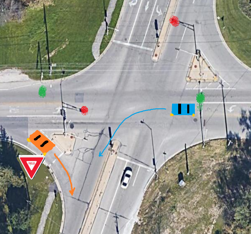
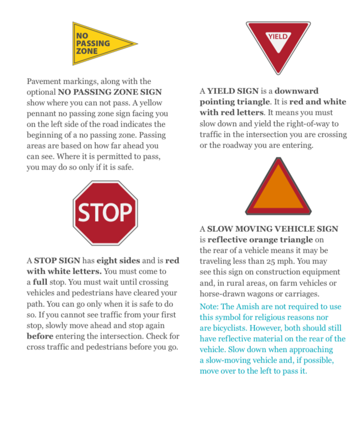
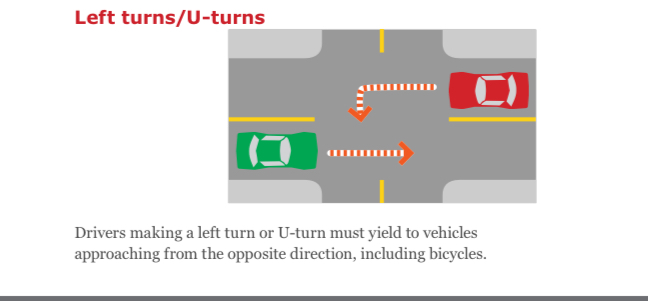
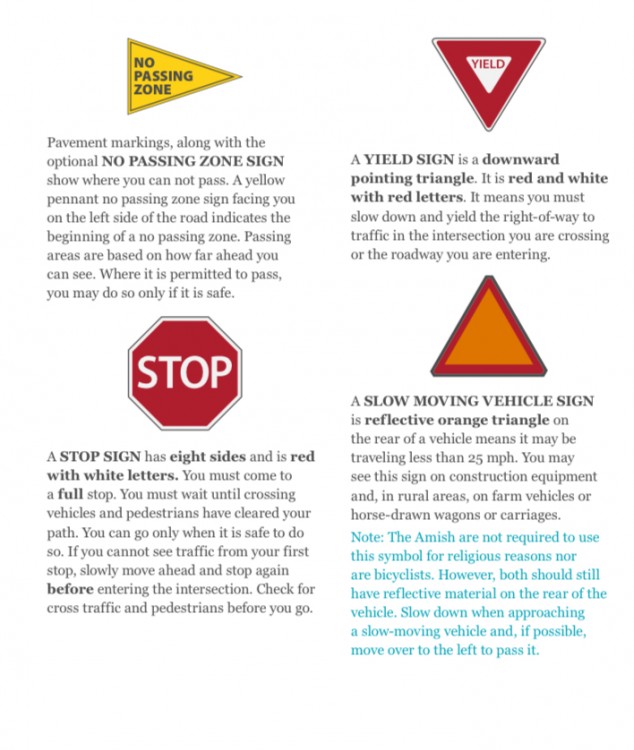
I don't claim to be an elite driver who could host professional coaching sessions for the next generation of prospective Drivers Ed instructors. I just drive the roads and try not to get in anyone's way. Can someone please explain how to navigate 2 stupid and contradictary intersection scenarios encountered in Wisconsin? 1) Controlled 4-way intersection with right turn yield sign 2) Controlled 4-way intersection with right turn stop sign I could be either car, the Limerock Orange car turning right on a green light (with yield sign) or the Yas Marina blue car turning left on the green light. I read the WI drivers instruction book. Here are the conflicts. A) Left turns yield to vehicles approaching from the opposite direction (I agree) Yield sign means you must yield the right of way C) Stop sign means you must come to a full stop. You can go only when it is safe to do so. What I observe in the wild is that people typically yield and people typically stop. But why?!? Why not just save the money on the signage and default to point A above? I have a feeling that the correct answer is that on a green light you still have to yield and still have to stop, but it just overcomplicates things when the world can operate simply on point A where left always yields to right. Discuss

-
I learned something that I think @m42b32 discovered on his M54 swap, which is: the ECU on a car with an electric throttle body does not open the throttle 100% all the time. It is programmed to open to a fraction of WOT depending on the RPM. I'm not sure if the strategy is to avoid lean spikes/NOx emissions (very likely), or better control of enrichment to prevent bogging and keep particulates down (probably not). I observed this while diagnosing a bad throttle body/TPS on a car (not a BMW) I was working on while plotting the throttle opening vs resistance. It only opened 50% max when the pedal was applied 100% from idle speed, and continues to open up a fraction of WOT until you are higher in the rev range where the volumetric efficiency will allow more complete cylinder filling. On Nissan products I believe people refer to this as "Torque Limiting" and sometimes this throttle restriction is removed when a performance tune is flashed. I do think this concept is known about but misunderstood since I think some people believe the reason is to protect the drivetrain. If anyone else has more information on this, chime in. I like this kind of stuff
-
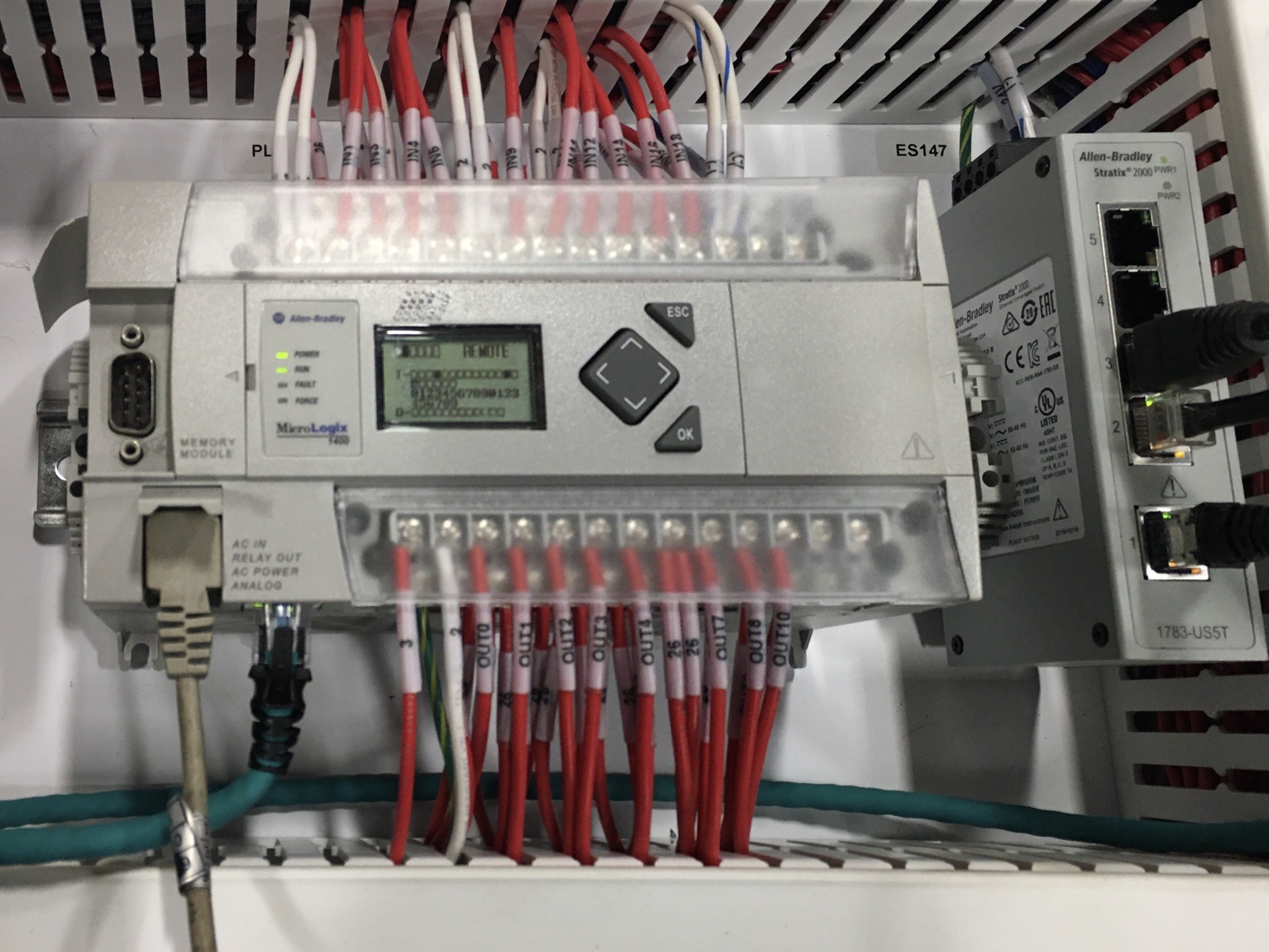
Does anyone have experience doing PLC programming, or setting up Micrologix controllers/Panelview displays? I no longer have a controls engineer at work and I have to get a machine programmed and debugged before Friday. I have never done this before and have managed to get the program loaded onto the controller and am now trying to load the display program to the Panelview, then get the comms setup. I have had many small miracles take place and with a measure of good luck, I may succeed tomorrow. In case I run into some dead ends, does anyone have experience that I may be able to lean on regarding loading and setup? Contractors/tech support has been hard to find and to receive Rockwell/AB tech support means renewing a 3 year service contract for $4000 that will very likely never be used again.

-
Is a ball-bearing turbo worth the added cost? or Is a quality name brand journal bearing single scroll turbo good enough? Is a split pulse/twin scroll turbo a "must-have" feature even though it requires two wastegates? https://turbobygarrett.com/turbobygarrett/journal_bearings_vs_ball_bearings "Turbo Response – When driving a vehicle with the cartridge ball bearing turbocharger, you will find exceptionally crisp and strong throttle response. Garrett Ball Bearing turbochargers spool up 15% faster than traditional journal bearings. This produces an improved response that can be converted to quicker 0-60 mph speed. In fact, some professional drivers of Garrett ball-bearing turbocharged engines report that they feel like they are driving a big, normally aspirated engine. Tests run on CART turbos have shown that ball-bearings have up to half of the power consumption of traditional bearings. The result is faster time to boost which translates into better drivability and acceleration. On-engine performance is also better in the steady-state for the Garrett Cartridge Ball Bearing"
-
no this isnt a tuning thread, put your pitchforks down I want to make a Windows executable file (command prompt interface is fine) that asks for a user input (part number), does a windows file search for a pdf file with the same name as the part number, cuts and pastes the pdf from its current directory, and moves it to another directory. I have dabbled with C++ a smidgen and could likely complete this with some assistance from someone who might know how to call up those functions. or, do you know of any good windows macro programs? Anyone?
-
Bosch Motronic 1.1/1.3 BMW Motronic 1.1 and 1.3 are an evolution of the early Motronic EMS fitted to previous BMW vehicles during the early to middle 1980's. Motronic 1.1 was first fitted to some 6 cylinder models in 1987 and was superseded in 1988 by Motronic 1.3. The main differences between 1.1 and 1.3 concern the SD feature. 1987 versions of M1.1 contained some small differences to the 1988 version. The Motronic EMS is a fully integrated system that controls primary ignition, fuelling and idle control from within the same ECU. Although only 6 cylinder engines were equipped with M1.1, when M1.3 was introduced, both 4 and 6 cylinder engines were equipped with this later version. The ignition point and injection duration are jointly processed by the ECU so that the best moment for ignition and fuelling are determined for every operating condition. The injection function of the Motronic system is based on the well tried 'L' jetronic system, although a number of refinements have improved operation. A 55 pin connector and multi-plug connects the ECU to the battery, sensors and actuators. Basic ECU operation A permanent voltage supply is made from the vehicle battery to pin 18 of the ECU. This allows the self-diagnostic function to retain data of an intermittent nature. Once the ignition is switched on, a voltage supply to ECU pin 27 (not 1987 M1.1) and to the ignition coil is made from the ignition switch. This causes the ECU to connect pin 36 to earth, so actuating the main fuel injection relay. A relay switched voltage supply is thus made to ECU pin 37, from terminal 87 of the main fuel injection relay. The 1987 M1.1 system relay is connected to earth and not to the ECU. However, once the ignition is switched on the relay operation is similar to later models. The majority of sensors (other than those that generate a voltage such the CAS, CID, KS and OS), are now provided with a 5.0 volt reference supply from a relevant pin on the ECU. When the engine is cranked or run, a speed signal from the CAS causes the ECU to earth pin 3 so that the fuel pump will run. Ignition and injection functions are also activated. All actuators (Injectors, ISCV, CFSV etc), are supplied with nbv from the main relay and the ECU completes the circuit by pulsing the relevant actuator wire to earth. Signal processing Basic ignition timing is stored in a two dimensional map and the engine load and speed signals determines the ignition timing. The main engine load sensor is the AFS and engine speed is determined from the CAS signal. Correction factors are then applied for starting, idle, deceleration and part and full-load operation. The main correction factor is engine temperature (CTS). Minor correction to timing are made with reference to the ATS and TS signals. In addition, other factors that influence ignition timing are signals from the ElectronicThrottle Control, Automatic Stability Control, Engine Torque Control and Electronic Transmission Control where all or any of these components are so fitted. The basic AFR is also stored in a two dimensional map and the engine load and speed signals determines the basic injection pulse value. Motronic calculates the AFR from the AFS signal and the engine speed (CAS). The AFR and the pulse duration are then corrected on reference to ATS, CTS, battery voltage and position of the TS. Other controlling factors are determined by operating conditions such as cold start and warm-up, idle condition, acceleration and deceleration. In models with an ISCV, Motronic accesses a different map for idle running conditions and this map is implemented whenever the engine speed is at idle. Idle speed during warm-up and normal hot running conditions are maintained by the ISCV. However, Motronic makes small adjustments to the idle speed by advancing or retarding the timing, and this results in an ignition timing that is forever changing during engine idle. Adaptive function The ECU is adaptive to changing engine operating characteristics and constantly monitors the data from the various sensors (ie MAP, ATS, CTS and TPS). As the engine or its components wear, the ECU reacts to new circumstances by adopting the changed values as a correction to the basic Map. When the adaptive map is used in conjunction with the OS, Motronic is able to respond much more quickly and retain tighter control over the changing gases in the exhaust system. During closed loop operation the basic injection value is determined by the values stored in the map for a specific rpm and load. If the basic injection value causes exhaust emissions outside of the Lambda value (ie 0.98 to 1.04 AFR) the mixture would be too rich or too lean and the OS would signal Motronic which in turn will correct the mixture. However, this response takes a little time and so Motronic learns a correction value and adds this 'Adaptive' values to the basic map. From now on, under most operating conditions, the emissions will be very close to Lambda and so, after reference to the OS signal, the ECU will only need to make small corrections to keep it that way. Adaption and correction of the map occurs during the following engine operations. CFSV operation ISCV operation Idle mixture adjustment part load mixture adjustment Operation of the CFSV introduces a combustible mixture to the engine that is compensated for by the fuel evaporation adaptive correction values after detection by the OS. Self Diagnostic function The Motronic 1.3 system has a self-test capability that regularly examines the signals from engine sensors and internally logs a code in the event of a fault being present. This code can be extracted from the Motronic Serial Port by a suitable Fault Code Reader. If the fault clears, the code will remain logged until wiped clean with a suitable FCR, or until the engine has been started for more than 5 times - when the fault code is self initialising. An ECU that retains codes for faults of an intermittent nature is a valuable aid to fault diagnosis. Motronic 1.1 1987 to 1988: The ECU will store a maximum of 5 fault codes. Motronic 1.3 from 1989: The fault code memory is extended to contain all fault codes that are detected by the EMS. In vehicles sold in the USA, when the ECU detects that a some faults are present it earths pin 15 and the Check Engine warning lamp on the dash will light. The lamp will stay lit until the fault is no longer present. A warning lamp is not fitted to vehicles sold in other markets. The faults that will turn on the lamp are mainly those concerned with emissions. Other faults are logged by the ECU but the lamp will remain out. Limited Operating Strategy (LOS) In the event of a serious fault in one or more of the sensors or their wiring circuits, Motronic will substitute a fixed default value in place of the defective sensor. This procedure is often termed limp home. A serious fault occurs when the signal from the sensor is outside of its normal operating parameters. When operating in LOS the engine may actually run quite well with failure of one or more minor sensors. Since the substituted values are those of a hot engine, cold starting and running during the warm-up period may be less than satisfactory. Also, failure of a major sensor, ie the AFS, will tend to make driving conditions less easy. Once the fault has cleared, Motronic will once more accept the live signal from the sensor. The following LOS measures are taken in the event of a failure Component..............................Action AFS........................substitute values are calculated from the TS position. The load signal is fixed to 6.0 ms and the ignition timing to 20° BTDC once the TS contact is open. ATS........................substitute value of 50° C . A code will not be set, and LOS will not commence until a minimum of 3 minutes after engine start and the engine idling for a minimum of 30 seconds. CID sensor.............injectors are pulsed simultaneously CO pot..................substitute value of 2.77 volts CTS...................substitute value of 80° C if ATS value is greater than 20° . if ATS value is less than 20° , substitute value of ATS value for first three minutes after engine start-up. OS.....................substitute value, open loop control TS.....................substitute values, restricted engine operation Anti-theft protection When the drive-away code is entered upon the on-board computer, or when the anti-theft system is armed, a signal is sent to Motronic which switches off the ignition and injection functions. Automatic Stability Control (ASC) ASC is integrated with ABS and is located in the ABS Electronic Control Unit. The rotational speed of the wheels is monitored by the ABS ECU via the ABS wheel sensors. If the rotational speed between the driven and non-driven wheels is vastly different, the ECU interprets this as wheel spin. Depending on the degree of wheel spin, the ABS ECU may take one or more of the following actions. Instruct the Electronic Throttle Control to reduce the throttle opening angle. Instruct the Motronic ECU to retard the ignition timing angle. Instruct the Motronic ECU to cut off ignition and injection functions. Engine Drag Torque Control Torque control occurs when wheel slip occurs during deceleration. Engine Drag Torque Control is also integrated with ABS and is located in the ABS Electronic Control Unit. The rotational speed of the wheels is monitored by the ABS ECU via the ABS wheel sensors. If the rotational speed of the driven wheels is vastly different to the non-driven wheels during deceleration, the ECU interprets this as wheel spin. Depending on the degree of wheel spin, the ABS ECU may take one or more of the following actions. Instruct the Motronic ECU to de-activate the deceleration fuel cut-off function. Instruct the Electronic Throttle Control to adapt the throttle opening angle until wheel spin is reduced. Service lights There is a cluster of LED's on the dash: five green, one red and one Yellow. Up to five green LED's will light when the ignition is turned on. However, the LED's will extinguish once the engine is started. When the yellow light comes on , service is due. When the Red light comes on, this means that service is overdue by approximately 1000 miles & should be attended to immediately. Once the service has been completed, the service lights should be reset. Reference voltage Voltage supply from the ECU to many of the engine sensors is at a 5.0 volt reference level. This ensures a stable working voltage unaffected by variations in system voltage. The earth return connection for most engine sensors is made through an ECU pin that is not directly connected to earth. The ECU internally connects that pin to earth via one of the ECU pins that are directly connected to earth. Signal shielding To reduce RFI, a number of sensors (ie CAS, KS and OS) use a shielded cable. The shielded cable is connected to the main ECU earth wire at terminal 19 to reduce interference to a minimum. Maximum speed cut-off Once the engine speed reaches a pre-determined limit (4 cyl: 6200 ± 40), (6 cyl: 6400 ± 40), Motronic cuts off injector operation so limiting the maximum rpm possible. Deceleration fuel cut-off When the engine speed is above 1000 . . 1200 rpm with the throttle closed, Motronic cuts off injector operation and retards the ignition timing as an economy aid. As the engine speed falls below the threshold value, injection is re-instated and the timing advances. The point at which injection is re-instated depends upon engine temperature and the drop in rpm. CAS The CAS in the early Motronic system utilised two sensors to provide speed and position signals to the ECU. However, in M1.1/1.3 the primary signal to initiate both ignition and fuelling emanates from a single CAS mounted in proximity to the flywheel. The CAS consists of an inductive magnet that radiates a magnetic field. A number of steel pins are set into the periphery of the flywheel at 10 intervals. As the flywheel spins, and the pins are rotated in the magnetic field, an AC voltage signal is delivered to the ECU to indicate speed of rotation. In addition, a reference mark to TDC also indicates crankshaft position as the flywheel spins. The peak to peak voltage of the speed signal (when viewed upon an oscilloscope) can vary from 5 volts at idle to over 100 volts at 6000 rpm. Because computers prefer their data as on/off signals, an analogue to digital converter transforms the AC pulse into a digital signal. Ignition Data on load (AFS), engine speed (CAS), engine temperature (CTS) and throttle position (TS) are collected by the ECU, which then refers to a three dimensional digital map stored within its microprocessor. This map contains an advance angle for each operating condition, and thus the best ignition advance angle for a particular operating condition can be determined. Ignition timing It is not possible to adjust the ignition timing on the Motronic 1.3 system. Amplifier The Motronic amplifier contains the circuitry for switching the coil negative terminal at the correct moment to instigate ignition. The amplifier circuitry is contained within the ECU itself and the microprocessor holds a map containing the correct ignition dwell period for each condition of engine speed and battery voltage. The signal received by the amplifier from the trigger is of an insufficient level to complete the necessary coil switching. The signal is thus amplified to a level capable of switching the coil negative terminal. One disadvantage of an internal amplifier, is that if the amplifier fails, the whole ECU must be renewed. Dwell operation in Motronic is based upon the principle of the `constant energy current limiting' system. This means that the dwell period remains constant at around 4.0 to 5.0 ms, at virtually all engine running speeds. However, the dwell duty cycle, when measured in percent or degrees, will vary as the engine speed varies. A current limiting hump is not visible when viewing an oscilloscope waveform. Ignition coil The ignition coil utilises low primary resistance in order to increase primary current and primary energy. The amplifier limits the primary current to around 8 amps and this permits a reserve of energy to maintain the required spark burn time (duration). Distributor In the Motronic system, the distributor only contains secondary HT components (distributor cap, rotor and HT leads) and serves to distribute the HT current from the coil secondary terminal to each spark plug in firing order. Cylinder Identification (CID) An cylinder identification sensor is used to identify cylinder firing sequence. The sensor is connected around the HT lead of cylinder number 4 (4 cylinder) or cylinder number 6 (6 cylinder) adjacent to the distributor. As the HT pulses travel along the HT lead, a small AC signal is induced in the sensor and returned to the ECU. The ECU utilises an ADC to transform the signal into a digital pulse. Fuel injection The Motronic ECU contains a fuel map with an injector opening time for basic conditions of speed and load. Information is then gathered from engine sensors such as the AFS, CAS, CTS, and TS. As a result of this information, the ECU will look-up the correct injector pulse duration right across the engine rpm, load and temperature range. The injectors are arranged in two banks with injectors 1 and 3 (4 cylinder) or 1, 3 and 5 (6 cylinder comprising one bank, and injectors 2 and 4 (4 cylinder) or 2, 4 and 6 (6 cylinder) making up the other bank. Each bank is connected to the ECU via an independent ECU pin. The Motronic 1.1 & 1.3 multi-point injection system pulses the injectors semi-sequentially and once every two engine revolutions. During engine start-up below 600 rpm the ECU pulses all injectors simultaneously. Once 600 rpm has been attained and if the ECU has received a signal from the CID sensor, each injector bank will be pulsed alternatively according to which pair of cylinders are approaching TDC. If a signal is not received from the CID sensor the injectors will remain on simultaneous operation. However, if the CID sensor subsequently sends a signal to the ECU after the engine has commenced running, the ECU will pulse the injectors semi-sequentially after the next deceleration phase - even if the CID sensor then ceases to send a signal. During start-up from cold, injector pulse duration is increased to provide a richer air/fuel mixture and pulse frequency is also increased. In addition, the ignition timing is also retarded. Injector frequency & pulse duration and degree of timing retard depend upon the engine temperature both during start-up and immediately afterwards. If the engine is restarted within one minute of the first start occurance, less overall fuel is injected to reduce the risk of fuel flooding into the engine. Fuel injectors The fuel injector is a magnetically operated solenoid valve that is actuated by the ECU. Voltage to the injectors is applied from the main relay and the earth path is completed by the ECU for a period of time (called pulse duration) of between 1.5 and 10 milliseconds. The pulse duration is very much dependant upon engine temperature, load, speed and operating conditions. When the magnetic solenoid closes, a back EMF voltage of up to 60 volts is initiated. The fuel injectors are mounted in the inlet stubs to the engine inlet valves so that a finely atomised fuel spray is directed onto the back of each valve. Since the injectors are pulsed in two banks, fuel will briefly rest upon the back of a valve before being drawn into a cylinder. Air Flow Sensor (AFS) The AFS is located between the air filter and the throttle body. As air flows through the sensor it deflects a spring loaded vane (flap). The greater the volume of air, the more will the flap be deflected. The vane is connected to a wiper arm which wipes a potentiometer track and so varies the resistance of the track. This allows a variable voltage signal to be returned to the ECU. The voltage signal varies in proportion to the volume of air that flows through the vane. Three wires are used by the circuitry of this sensor and it is often referred to as a three wire sensor. A 5 volt reference voltage is applied to the resistance track with the other end connected to the AFS earth return circuit. The third wire is connected to the wiper arm. From the voltage returned, the ECU is able to calculate the volume of air (load) entering the engine and this is used to calculate the main fuel injection duration. To smooth out inlet pulses, a damper is connected to the AFS vane. The AFS exerts a major influence on the amount of fuel injected. ATS The ATS is mounted in the AFS inlet tract and measures the air temperature before it enters the inlet manifold. Because the density of air varies in inverse proportion to the temperature, the ATS signal allows more accurate assessment of the volume of air entering the engine. However, the ATS has only a minor correcting effect on ECU output. The open circuit supply to the sensor is at a 5.0 volt reference level and the earth path is through the AFS earth return circuit. The ATS operates on the NTC principle. A variable voltage signal is returned to the ECU based upon the air temperature. This signal is approximately 2.0 to 3.0 volts at an ambient temperature of 20° C and reduces to about 1.5 volt as the temperature rises to around 40° C. CO pot The CO pot mixture adjuster is a three wire potentiometer that allows small changes to be made to the idle CO. A 5.0 volt reference voltage is applied to the sensor and connected to the AFS earth return circuit. The third wire is the CO pot signal. As the CO pot adjustment screw is turned the change in resistance returns a voltage signal to the ECU that will result in a change in CO. The CO pot adjustment only affects idle CO. Datum position is usually 2.50 volts. On catalyst equipped models, the CO pot has no effect and the CO is thus non-adjustable. CTS The CTS is immersed in the coolant system and contains a variable resistance that operates on the NTC principle. When the engine is cold, the resistance is quite high. Once the engine is started and begins to warm-up, the coolant becomes hotter and this causes a change in the CTS resistance. As the CTS becomes hotter, the resistance of the CTS reduces (NTC principle) and this returns a variable voltage signal to the ECU based upon the coolant temperature. The open circuit supply to the sensor is at a 5.0 volt reference level and this voltage reduces to a value that depends upon the resistance of the CTS resistance. Normal operating temperature is usually from 80° to 100° C. The ECU uses the CTS signal as a main correction factor when calculating ignition timing and injection duration. Throttle switch A throttle switch with dual contacts is provided to inform the ECU of idle position, deceleration, cruising and full-load (WOT) conditions. When the engine is at idle the idle contact is closed and the full-load contact is open. As the throttle is moved to the fully open position, the full-load contact closes and the idle contact becomes open. Under cruising conditions with a part-open throttle, both contacts are open. During full-load operation, the ECU provides additional enrichment. During closed throttle operation above a certain rpm (deceleration), the ECU will cut-off fuel injection. Injection will be reintroduced once the rpm returns to idle or the throttle is opened. Electronic throttle control Some models are equipped with Electronic throttle control, the so-alled 'drive by wire' system whereby the mechanical control using a throttle cable is discontinued. A TS is not used on vehicles equipped with Electronic throttle control and the position of the throttle valve is signalled to the ECU electronically. ISCV (2 wire type) The ISCV is a solenoid controlled actuator that the Motronic ECU uses to automatically control idle speed during normal idle and during engine warm-up. Motronic detects the engine idle situation from the position of the TS or TPS. The ISCV is located in a hose that connects the inlet manifold to the air filter side of the throttle plate. A voltage supply is applied from the main relay and the ISCV earth is actuated by the ECU according to load. When an electrical load, such as headlights, A/C or heater fan etc are switched on, the idle speed would tend to drop. The ECU will sense the load and rotate the ISCV against spring tension to increase the air flow through the valve and thus increase the idle speed. When the load is removed, the ECU will pulse the valve so that the air flow is reduced. Normal idle speed should be maintained under all cold and hot operating conditions. If the ISCV fails it will fail in a fail-safe position with the aperture almost closed. This will provide a basic idle speed. ISCV (3 wire type) The ISCV is a solenoid controlled actuator that the Motronic ECU uses to automatically control idle speed during normal idle and during engine warm-up. The ISCV is located in a hose that connects the inlet manifold to the air filter side of the throttle plate. Unlike the two pin ISCV which is controlled by a separate Idle speed ECU, the 3 pin ISCV is controlled by the Motronic ECU via ECU pins 33 and 34. The ISCV is a DC motor that the ECU can rotate either clockwise or anti-clockwise. Rotating in one direction will open the valve and rotating in the opposite direction will cause it to close. A voltage supply is applied to the ISCV from the battery and the earth for the motor is made through two connections to the ECU. Rotation of the motor in the appropriate direction is accomplished by actuating the motor through one or the other of the earth circuits. In reality the two circuits are opposed. This prevents the valve from being fully opened of closed in one particular direction. The valve will thus take up an average position that reflects circuit bias to be open or closed. Normally, this bias would be towards the open position. A duty cycle can be measured on each earth circuit to determine the opening or closing time period as a percentage of the total time available. When an electrical load, such as headlights or heater fan etc are switched on, the idle speed would tend to drop. The idle ECU will sense the load and rotate the ISCV to increase the air flow through the valve and thus increase the idle speed. When the load is removed, the ECU will pulse the valve so that the air flow is reduced. Normal idle speed should be maintained under all cold and hot operating conditions. If the ISCV fails it will fail in a fail-safe position with the aperture almost closed. This will provide a basic idle speed. Relays The Motronic electrical system is controlled by a main fuel injection relay and a fuel pump relay. A permanent voltage supply is made to the main relay terminals 30 and 86 from the battery positive terminal. When the ignition is switched on, the ECU earths terminal 85 through ECU terminal number 36 which energises the first relay winding (on the 1987 M1.1 system, this connection was made directly to earth). This causes the first relay contacts to close and terminal 30 is connected to the output circuit at terminal 87. A voltage supply is thus output at terminal 87. Terminal 87 supplies voltage to the injectors, ECU terminal 37, ISCV and the CFSV when fitted. In addition voltage is supplied to the fuel pump relay terminal 86. When the ignition is switched on. the ECU briefly earths fuel pump relay contact 85 at ECU terminal 3. This energises the relay winding, which closes the relay contact and connects voltage from terminal 30 to terminal 87, thereby providing voltage to the fuel pump circuit. After approximately one second, the ECU opens the circuit and the pump stops. This brief running of the fuel pump allows pressure to build within the fuel pressure lines, and provides for an easier start. The fuel pump relay circuit will then remain open until the engine is cranked or run. Once the ECU receives a speed signal from the CAS, the relay winding will again be energised by the ECU, and the fuel pump will run until 3 seconds after the engine is stopped. The 3 seconds delay in switching off the pump relay allows the fuel pump to maintain pressure on engine shut-off to avoid engine run-on. In addition, on some vehicles control of the OS heater is made through a separate OS relay. Once the ignition is switched on, a voltage supply is made to the OS heater relay terminals 30 and 86. When the engine is started, the ECU connects relay terminal 85 to earth through ECU pin 23. The relay actuates and the output voltage at terminal 87 provides voltage to the OS heater. The ECU switches off the relay under certain conditions of speed and load. Fuel pressure system From build date 3/1988 the BMW vehicles in the Motronic 1.3 range were mounted internally in the fuel tank. Prior to that date the pump was mounted externally and in some instances an additional internal transfer pump was fitted to aid the pumping of fuel from the fuel tank. internal pump operation (where fitted) The fuel pump assembly comprises an outer and inner gear assembly termed a gerotor. Once the pump motor becomes energised, the gerotor rotates and as the fuel passes through the individual teeth of the gerotor, a pressure differential is created. Fuel is drawn through the pump inlet, to be pressurised between the rotating gerotor teeth and discharged from the pump outlet into the fuel supply line. When both an internal and external pump are fitted, the internal pump is ancillary to the main external pump and is provided to aid the pumping of fuel from the fuel tank. external pump operation (where fitted) A roller type fuel pump, driven by a permanent magnet electric motor mounted close to the fuel tank draws fuel from the tank and pumps it to the fuel rail via a fuel filter. The pump is of the 'wet' variety in that fuel actually flows through the pump and the electric motor. There is no actual fire risk because the fuel drawn through the pump is not in a combustible condition. Mounted upon the armature shaft is an eccentric rotor holding a number of pockets arranged around the circumference - each pocket containing a metal roller. As the pump is actuated, the rollers are flung outwards by centrifugal force to act as seals. The fuel between the rollers is forced to the pump pressure outlet. Fuel pressure in the fuel rail is maintained at a constant 2.5 bar by a fuel pressure regulator. The fuel pump normally provides much more fuel than is required, and surplus fuel is thus returned to the fuel tank via a return pipe. In fact, a maximum fuel pressure in excess of 5 bar is possible in this system. To prevent pressure loss in the supply system, a non-return valve is provided in the fuel pump outlet. When the ignition is switched off, and the fuel pump ceases operation, pressure is thus maintained for some time. Fuel pressure regulator The pressure regulator is fitted on the outlet side of the fuel rail and maintains an even pressure of 2.5 bar in the fuel rail. The pressure regulator consists of two chambers separated by a diaphragm. The upper chamber contains a spring which exerts pressure upon the lower chamber and closes off the outlet diaphragm. Pressurised fuel flows into the lower chamber and this exerts pressure upon the diaphragm. Once the pressure exceeds 2.5 bar, the outlet diaphragm is opened and excess fuel flows back to the fuel tank via a return line. A vacuum hose connects the upper chamber to the inlet manifold so that variations in inlet manifold pressure will not affect the amount of fuel injected. This means that the pressure in the rail is always at a constant pressure above the pressure in the inlet manifold. The quantity of injected fuel thus depends solely on injector opening time, as determined by the ECU, and not on a variable fuel pressure. At idle speed with the vacuum pipe disconnected, or with the engine stopped and the pump running, or at WOT the system fuel pressure will be approximately 2.5 bar. At idle speed (vacuum pipe connected), the fuel pressure will be approximately 0.5 bar under the system pressure. Catalytic Converter and emission control The Motronic injection system fitted to BMW vehicles equipped with a Catalytic Converter implements a closed loop control system so that exhaust emissions may be reduced. Closed loop systems are equipped with an oxygen sensor which monitors the exhaust gas for oxygen content. A low oxygen level in the exhaust signifies a rich mixture. A high oxygen level in the exhaust signifies a weak mixture. The Oxygen Sensor closed loop voltage is quite low and switches between 100 mVolts (weak) to 1.0 volt (rich). The signal actually takes the form of a switch and switches from weak to rich at the rate of approximately 1 HZ. A digital voltmeter connected to the signal wire, would display.an average voltage of approximately 0.45 volts. In the event of OS circuit failure, the ECU substitutes a constant voltage of 0.45 volts and this should not be confused with the average voltage of 0.45 which occurs during switching from approximately 1.0 volt to 0.1 volt. When the engine is operating under closed loop control, the OS signal causes the ECU to modify the injector pulse so that the AFR is maintained close to the stoichiometric ratio. By controlling the injection pulse, during most operating conditions, so that the air/ fuel ratio is always in a small window around the Lambda point (ie Lambda = 0.98 to 1.04), almost perfect combustion is achieved. Thus the Catalyst has less work to do and it will last longer with fewer emissions at the tail pipe. The closed loop control is implemented during engine operation at engine normal operating temperature. When the coolant temperatures is below 70° C, or the engine is at full load or is on the overrun the ECU will operate in open loop. When operating in open loop, the ECU allows a richer or leaner AFR than the stoichiometric ratio. This prevents engine hesitation, for example, during acceleration with a wide open throttle. The OS only produces a signal when the exhaust gas, has reached a minimum temperature of approximately 300° C. In order that the OS will reach optimum operating temperature as quickly as possible after the engine has started, the OS contains a heating element. The OS heater is controlled by the ECU through an OS relay or from the fuel pump relay depending on vehicle. The ECU switches off the OS relay under certain conditions of speed and load. CFSV A CFSV and activated carbon canister is employed to aid evaporative emission control. The carbon canister stores fuel vapours until the CFSV is opened by Motronic under certain operating conditions. Once the CFSV is actuated by the EMS, fuel vapours are drawn into the inlet manifold to be burnt by the engine during normal combustion.
-
Saw this in the Pelican Parts newsletter http://germancarsforsaleblog.com/wagon-week-1997-bmw-alpina-b6-2-8-touring/
-
Sup.